
Views: 0 Author: Site Editor Publish Time: 2026-08-31 Origin: Site


An industrial PC is only as effective as its ability to communicate with the plant floor. Mismatched or inadequate I/O configurations lead to data bottlenecks, forced reliance on failure-prone adapters, and costly deployment delays. System integrators and engineers face the challenge of bridging legacy equipment (which relies on serial or analog signals) with modern edge devices (requiring high-bandwidth Ethernet or PoE) within a single, reliable hardware footprint.
Specifying the correct I/O requires a systematic audit of all connected equipment, understanding the physical and protocol requirements of each device, and evaluating the trade-offs between fixed, modular, and expandable computing architectures.
Audit Before Specification: Categorizing connected devices by bandwidth, protocol, and power requirements prevents over-engineering and eliminates connectivity gaps.
Plan for Phased Scaling: Plant floors evolve. A system might start connected to a single PLC but must be capable of scaling to support additional variable frequency drives (VFDs), meters, and barcode scanners over time.
Modularity vs. Footprint: Expandable systems offer future-proofing for evolving PLC and sensor networks, while fixed-I/O systems maximize reliability in harsh, space-constrained environments.
Isolation is Critical: Industrial environments require optically isolated ports to protect the CPU from voltage spikes and electromagnetic interference (EMI) generated by heavy machinery.
Software Mapping Matters: Physical I/O must align with the control software’s ability to map physical points to memory addresses efficiently.
Defining success for an I/O configuration goes far beyond counting the number of available ports on a chassis. A successful deployment achieves zero data packet loss, maintains sub-millisecond latency for critical motion control, and completely eliminates the need for consumer-grade dongles or fragile converters on the DIN rail. Every connection must be native, secure, and built to withstand harsh environmental conditions. When you deploy an Industrial PC, the I/O panel acts as the central nervous system for your entire automation cell, routing logic, power, and safety signals simultaneously.
Misaligning your I/O specifications carries heavy operational risks. Under-specifying your ports leaves you unable to add future programmable logic controllers (PLCs) or variable frequency drives without overhauling the hardware. You end up daisy-chaining unmanaged switches or relying on USB hubs, which introduces latency and points of failure. Conversely, over-specifying leads to unnecessary hardware complexity and increased thermal output. Extra ports consume power and generate heat. In a sealed, fanless environment, unmanaged heat degrades component lifespan and leads to CPU throttling during peak processing loads.
Engineers must clearly differentiate between physical port compatibility and protocol compatibility. Having an RJ45 port does not guarantee communication with a drive or sensor. The network interface card (NIC) must support the specific industrial protocol required by your equipment. EtherNet/IP, PROFINET, and EtherCAT all use standard Ethernet cables but process data entirely differently at the MAC and software levels. Hardware must support these protocols natively to ensure deterministic communication. For example, EtherCAT requires specific Intel MAC controllers to handle distributed clocks accurately; a generic Realtek chip will fail to maintain the required cycle times.
Plant floors undergo phased deployments. An industrial computer must be configured for today's single-PLC setup while anticipating tomorrow's upgrades. Facilities continuously integrate additional remote devices, smart meters, and edge AI peripherals. Planning your I/O for a three-to-five-year expansion window prevents premature hardware obsolescence and keeps production lines running during upgrades. You can categorize these deployment phases to better map your hardware needs:
Initial Commissioning: Connecting the primary PLC, local HMI, and basic safety relays.
Process Optimization: Adding secondary sensors, barcode scanners, and vision systems for automated quality control.
Facility Integration: Tying the local machine network into the broader plant SCADA system or pushing telemetry data to an edge server.
Establishing a framework to categorize plant-floor devices is the first step in determining exact I/O requirements. You must map out every sensor, drive, camera, and actuator. Grouping these requirements by use case streamlines the hardware selection process and prevents omissions during the specification phase. You cannot simply guess the port count; you must trace the signal path for every piece of hardware on the machine.
Application-specific I/O profiles help clarify hardware needs. Machine vision applications demand high bandwidth and power delivery, often requiring Power over Ethernet (PoE) or GigE ports capable of handling jumbo frames. Process control applications lean heavily on legacy serial connections and Digital I/O (DIO) for valve and relay control. By profiling the application first, you narrow down the motherboard and expansion requirements immediately.
Legacy control systems remain prevalent in modern factories. Older PLCs, CNC machines, and industrial barcode scanners frequently rely on RS-232, RS-422, or RS-485 serial interfaces. These connections require native COM ports on the computer chassis. Emulating these ports through USB adapters introduces latency and driver instability, which causes communication timeouts in continuous production environments. When auditing serial devices, you must also document the required baud rate, parity, and whether the RS-485 network requires internal termination resistors.
High-bandwidth peripherals represent the opposite end of the spectrum. Machine vision cameras, LiDAR sensors, and high-resolution Human Machine Interfaces (HMIs) push massive amounts of data. These devices require dedicated Gigabit Ethernet, USB 3.2, and PoE. PoE simplifies wiring by delivering both data and power over a single Cat6 cable, but it requires specialized network controllers on the PC and a power supply capable of handling the extra wattage.
Sensors and actuators handle the basic physical interactions of the machine. Environmental sensors, safety relays, and limit switches typically connect via Digital I/O (DIO) or General Purpose I/O (GPIO). Mapping these connections ensures the computer can trigger local alarms or read simple states without routing every signal through a separate, external PLC. You must determine if your DIO needs to be sinking (NPN) or sourcing (PNP) to match your field sensors.
Motion control and drives demand the strictest connectivity standards. Variable frequency drives (VFDs) and servo motors require low-latency, deterministic communication. This usually dictates dedicated Ethernet ports running EtherCAT or PROFINET. Any jitter or packet loss here results in physical machine errors, ruined materials, or safety hazards. You must isolate this motion control traffic from general plant network traffic.
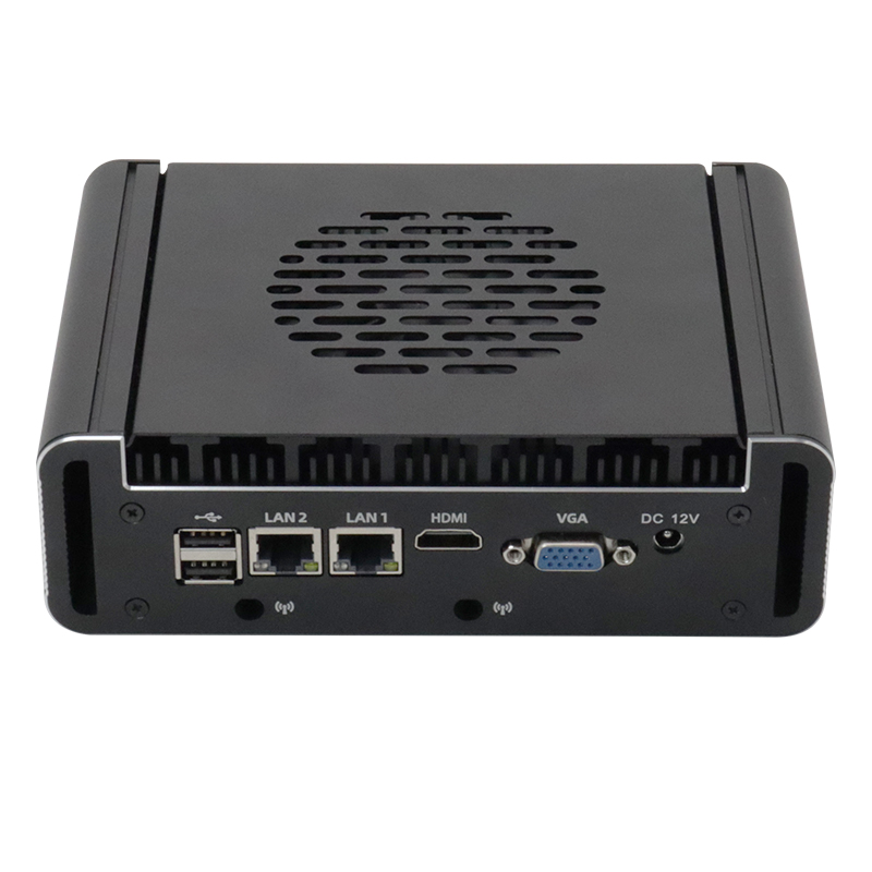
Specific port types translate directly to operational reliability. Evaluating these connections requires looking at physical durability, signal integrity, and bandwidth capacity. Every port choice impacts how the machine performs under vibration, electrical noise, and continuous operation. You must match the physical connector to the environmental reality of the installation site.
Native COM ports provide secure, locking connections for serial data. They are vastly superior to USB for legacy equipment. USB connectors lack mechanical retention and vibrate loose on stamping presses or CNC machines. Native serial ports use DB9 connectors with locking screws, ensuring the cable remains seated regardless of physical shock. Furthermore, native COM ports interface directly with the motherboard's UART, providing a stable hardware-level interrupt that USB-to-serial chips cannot replicate.
Ethernet and LAN configurations require careful network segmentation. Factory environments must separate IT networks from OT control networks to maintain security and bandwidth. This necessitates multiple independent LAN ports on the computer. One port handles outbound data to the cloud or factory server, while the others manage local machine control traffic without interference. Using a single port and a managed switch introduces a single point of failure and complicates IP addressing.
Deciding between local and remote I/O expansion impacts cabinet wiring. Native ports on the computer are ideal for localized machines where all sensors are within a few meters. However, sprawling facilities benefit from remote I/O blocks connected via EtherNet/IP. This distributes connectivity across the plant, reducing long cable runs and simplifying troubleshooting at the machine level. You run one Ethernet cable to a remote block instead of pulling fifty discrete wires back to the main cabinet.
Native DIO allows the computer to interact directly with the physical world. It can trigger stack lights, control pneumatic valves, or read proximity sensors instantly. This bypasses the latency of sending signals to a network PLC and back, enabling faster local reaction times for safety and process limits. Optically isolated DIO protects the motherboard from inductive kickback when switching heavy relay coils.
I/O Type | Typical Connected Equipment | Common Protocols / Standards | Primary Advantage |
|---|---|---|---|
Serial (RS-232/422/485) | Legacy PLCs, CNCs, Barcode Scanners | Modbus RTU, ASCII | High reliability, locking connectors, long cable runs (RS-485). |
Gigabit LAN (RJ45/M12) | VFDs, Servo Drives, Remote I/O | EtherNet/IP, PROFINET, EtherCAT | Deterministic control, network segmentation, high bandwidth. |
Power over Ethernet (PoE) | Machine Vision Cameras, LiDAR, IP Phones | IEEE 802.3af/at (GigE Vision) | Combines power and data, simplifies cable routing. |
Digital I/O (DIO) | Relays, Limit Switches, Stack Lights | High/Low Voltage Signals (24VDC) | Direct hardware control, ultra-low latency, local triggering. |
USB 3.2 | Modern Peripherals, Local HMIs, Diagnostics | USB Mass Storage, HID | High speed data transfer, universal compatibility. |
Balancing specific I/O needs against environmental durability and physical space dictates the hardware form factor. You must weigh the desire for infinite expansion against the realities of dust, moisture, and tight control cabinets. Every expansion slot introduces potential ingress points and thermal challenges. You cannot put a fully vented, actively cooled tower PC inside a dusty sawmill and expect it to survive.
A fanless industrial box PC offers maximum reliability for fixed I/O configurations. Eliminating expansion slots reduces the chassis size and improves the ingress protection (IP) rating. Without fans or vents, dust, metallic shavings, and airborne oil cannot enter the system. This maximizes the Mean Time Between Failures (MTBF) in harsh, space-constrained environments where maintenance access is difficult. You specify the exact ports you need upfront, and the system runs untouched for years.
An embedded industrial computer with modular I/O provides a strong middle ground. These systems utilize proprietary modular blocks. You can add a module for extra COM ports or isolated LAN ports without changing the core motherboard. This allows for customized connectivity while maintaining a sealed, fanless chassis design. If a specific port gets damaged by a voltage spike, you replace the module rather than the entire computer.
PCIe and PCI expansion systems are necessary for highly specialized applications. Frame grabbers for high-speed vision, proprietary fieldbus cards, or dedicated AI accelerators require full-size expansion slots. However, these cards generate significant heat. Accommodating them increases the system footprint and often requires active cooling, which lowers the overall environmental rating of the deployment. You must calculate the thermal dissipation of the add-in card and ensure the chassis can handle the load.
Installation methods heavily impact physical access to I/O ports. DIN-rail mounting is standard in control cabinets, but it restricts cable bend radii. Thick, shielded Cat6a cables or heavy DB9 connectors require several inches of clearance. VESA or panel mounting changes how cables route away from the chassis. You must account for cable management, heavy connector clearance, and strain relief when selecting the physical layout of the I/O panel. A port is useless if you cannot physically plug a cable into it once the door is closed.
Deploying complex I/O configurations introduces physical and software risks. Long-term operation requires mitigating electrical interference, managing thermal loads, and ensuring software correctly interprets physical signals. Ignoring these factors leads to intermittent failures that are notoriously difficult to diagnose in the field.
Electromagnetic interference (EMI) and ground loops plague factory environments. Heavy machinery, welding equipment, and large motors generate voltage transients that travel down copper cables. Mitigate this by specifying optically isolated COM and DIO ports. Isolation creates a physical barrier using light to transmit signals, preventing high-voltage spikes from reaching and destroying the motherboard. Without isolation, a ground fault on a remote sensor will fry the entire computer.
Thermal throttling is a severe risk when powering multiple peripherals. High-draw PCIe cards and PoE cameras pull significant wattage through the computer. This heat must be dissipated. Verify the system's wide-temperature ratings and calculate the total power draw. Ensure stable power input during installation and provide adequate spacing around the chassis for convection cooling. If you pull 60 watts of PoE power through a fanless chassis, the external heatsink fins must have unobstructed airflow.
Hardware and software integration presents a final hurdle. The CPU must be configured in the BIOS or operating system to recognize new hardware modules. Furthermore, physical I/O points must be correctly mapped to memory addresses in control software like Studio 5000 or TwinCAT. If the logical mapping does not match the physical wiring, the control program will fail to execute commands, leading to immediate operational faults. You must document the exact memory address for every physical pin during the commissioning phase.
The optimal I/O configuration is rarely the one with the most ports. It is the one that directly maps to your audited equipment list while leaving a calculated margin for future expansion. Over-specifying wastes budget and complicates thermal management, while under-specifying guarantees future deployment bottlenecks. You must approach the specification process as an engineering exercise, not a simple shopping list.
Start your shortlisting process with a strict inventory of current and future devices. Determine your environmental and mounting constraints to decide between a fanless box PC and an actively cooled expansion system. Finally, filter your hardware choices based on the necessity for optical isolation and specific power delivery requirements.
Document the exact power draw, voltage logic, and protocol requirements for every peripheral on your machine.
Map out your network architecture to determine how many independent LAN ports are needed for IT/OT segmentation.
Verify the physical dimensions of your control cabinet to ensure adequate clearance for heavy locking connectors and cable bend radii.
Consult with an industrial computing specialist to validate motherboard compatibility with your required expansion cards.
A: Yes, depending on the chassis. Modular I/O blocks allow port additions without opening the case. PCIe expansion systems accept standard add-in cards. You can also use remote I/O blocks via Ethernet. However, fixed-chassis fanless designs cannot be internally expanded once deployed.
A: Isolated ports use optical components to separate the external connection from the internal motherboard circuitry. This prevents electrical damage from power surges, ground loops, and EMI. Non-isolated ports lack this protection and are vulnerable to voltage spikes common in heavy industrial environments.
A: Native COM ports provide superior reliability. They feature physical locking mechanisms that prevent accidental disconnection under vibration. They also offer stable hardware-level drivers, avoiding the latency, driver conflicts, and connection drops frequently associated with consumer-grade USB-to-Serial adapters.
A: You connect them using native RS-232, RS-422, or RS-485 serial ports. You must ensure the physical wiring matches the PLC's terminal block. Additionally, you must configure the software to match the exact baud rate, parity, and communication protocol used by the legacy PLC.
A: Yes. PoE controllers generate additional heat as they route power to external devices like cameras. Supplying 15W to 30W per port increases the internal thermal load. Fanless systems must have adequate heat sinks and be rated for this extra thermal output to prevent CPU throttling.
A: The CPU is first configured to recognize the local or remote hardware modules. In software environments like Studio 5000, engineers assign specific memory addresses to the physical ports. This logical mapping allows the control program to read inputs and trigger outputs accurately.


